| Model | Speed (rpm) 50HZ | Capacity *1 (L/min) | Ultimate vacuum *2 (kPa) | Continuous vacuum *3 (kpa) |
Continuous blower *3 (kpa) |
Motor I/O port | Motor Voltage | Motor Output (kW) | Mass(kg) | |
|---|---|---|---|---|---|---|---|---|---|---|
| 50HZ | 60HZ | |||||||||
| KRX1-L-V | 1400 | 135 | 155 | 79 | 60 | - | Rc 3/4 | 3PH415V50Hz | 0.18 | 16 |
| KRX1-L-B | 1400 | 135 | 155 | - | - | 60 | Rc 3/4 | 3PH415V50Hz | 0.18 | 16 |
| KRX1-L-VB | 1400 | 135 | 155 | 79 | V+B≤60 | Rc 3/4 | 3PH415V50Hz | 0.18 | 16 | |
| KRX3-L-V | 1400 | 235 | 280 | 84 | 60 | - | Rc 3/4 | 3PH415V50Hz | 0.37 | 21.5 |
| KRX3-L-B | 1400 | 235 | 280 | - | - | 60 | Rc 3/4 | 3PH415V50Hz | 0.37 | 21.5 |
| KRX3-L-VB | 1400 | 235 | 280 | 84 | V+B≤60 | Rc 3/4 | 3PH415V50Hz | 0.37 | 21.5 | |
| KRX5-L-V | 1400 | 405 | 480 | 86 | 60 | - | Rc 3/4 | 3PH415V50Hz | 0.75 | 33 |
| KRX5-L-B | 1400 | 405 | 480 | - | - | 60 | Rc 3/4 | 3PH415V50Hz | 0.75 | 33 |
| KRX5-L-VB | 1400 | 405 | 480 | 86 | V+B≤60 | Rc 3/4 | 3PH415V50Hz | 0.75 | 33 | |
| KRX6-L-V | 1400 | 575 | 685 | 86 | 60 | - | Rc 3/4 | 3PH415V50Hz | 1.5 | 40 |
| KRX6-L-B | 1400 | 575 | 685 | - | - | 60 | Rc 3/4 | 3PH415V50Hz | 1.5 | 40 |
| KRX6-L-VB | 1400 | 575 | 685 | 86 | V+B≤60 | Rc 3/4 | 3PH415V50Hz | 1.5 | 40 | |
| KRX7A-L-V | 1400 | 1190 | - | 90 | 60 | - | Rc 1 | 3PH415V50Hz | 2.2 | 68 |
| KRX7A-L-B | 1400 | 1190 | - | - | - | 60 | Rc 1 | 3PH415V50Hz | 2.2 | 68 |
| KRX7A-L-VB | 1400 | 1190 | - | 90 | V+B≤60 | Rc 1 | 3PH415V50Hz | 2.2 | 68 | |
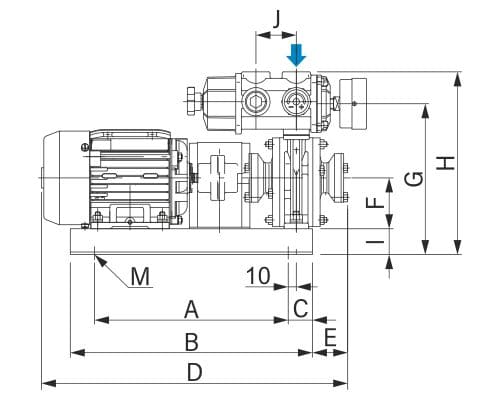
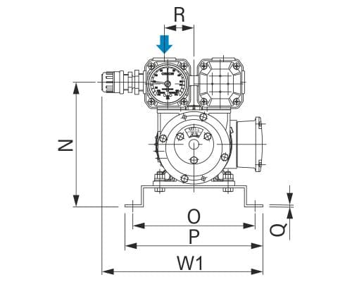
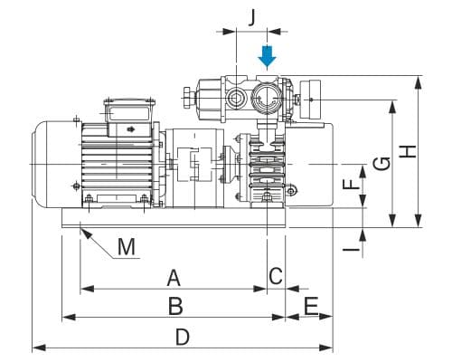
| Model (mm) | H | D | W1 | W2 | W3 | A | B | C | E | F | G | I |
|---|---|---|---|---|---|---|---|---|---|---|---|---|
| KRX1-L (-V, -B, -VB) | (227) | (380)* | (245) | (245) | (280) | 240 | 300 | 30 | (44) | 63 | (187) | 32 |
| KRX3-L (-V, -B, -VB) | (248) | (490)* | (270) | (272) | (312) | 304 | 364 | 30 | (77) | 71 | (208) | 32 |
| KRX5-L (-V, -B, -VB) | (250) | (542)* | (270) | (272) | (312) | 340 | 402 | 31 | (83) | 80 | (210) | 32 |
| KRX6-L (-V, -B, -VB) | (273) | (664)* | (276) | (278) | (312) | 420 | 470 | 25 | (102) | 90 | (233) | 38 |
| KRX7A-L (-V, -B, -VB) | (325) | (767)* | (326) | (333) | (379) | 430 | 530 | 50 | (136) | 100 | (270) | 38 |
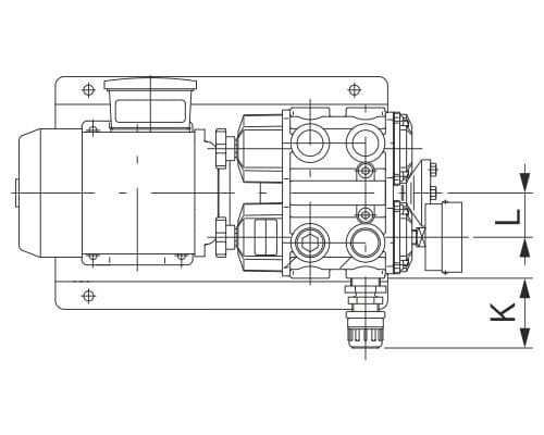
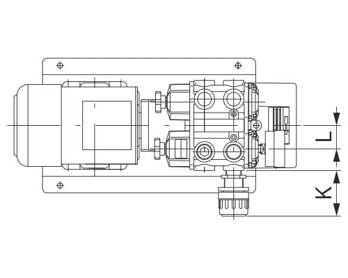
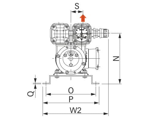
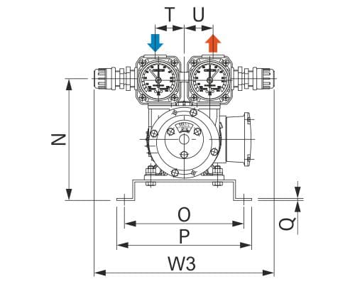
| Model (mm) | J | K | L | M | N | O | P | Q | R | S | T | U |
|---|---|---|---|---|---|---|---|---|---|---|---|---|
| KRX1-L (-V, -B, -VB) | 50 | (63) | 40 | 4-φ9 | (190) | 186 | 210 | 3.2 | 45 | 45 | 45 | 45 |
| KRX3-L (-V, -B, -VB) | 50 | (78) | 40 | 4-φ9 | (211) | 205 | 230 | 4.5 | 45 | 45 | 45 | 45 |
| KRX5-L (-V, -B, -VB) | 50 | (78) | 40 | 4-φ9 | (213) | 205 | 230 | 4.5 | 45 | 45 | 45 | 45 |
| KRX6-L (-V, -B, -VB) | 50 | (78) | 40 | 4-φ10 | (236) | 220 | 242 | 4.5 | 45 | 45 | 45 | 45 |
| KRX7A-L (-V, -B, -VB) | 70 | (86) | 50 | 4-φ12 | (270) | 250 | 280 | 4.5 | 55 | 55 | 55 | 55 |
* Dimensions are for V type. * Reference data with standard motor
.jpg)
-L-B.jpg)
-L-VB.jpg)